

.png.c9b8f3e9eda461da3c0e9ca5ff8c6888.png)
In this article, we will use esp8266 to combine with relays to make a simple smart plug-in board.
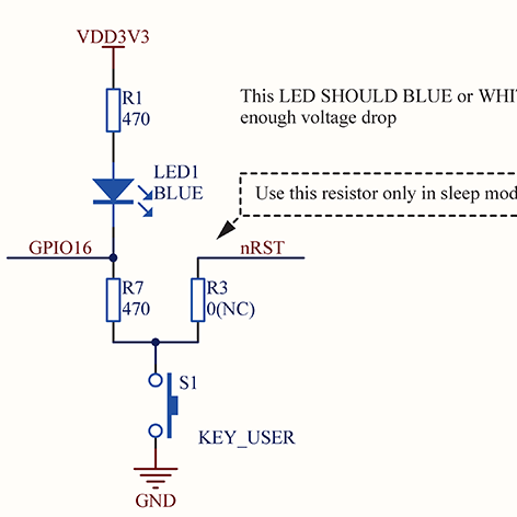
Route Map
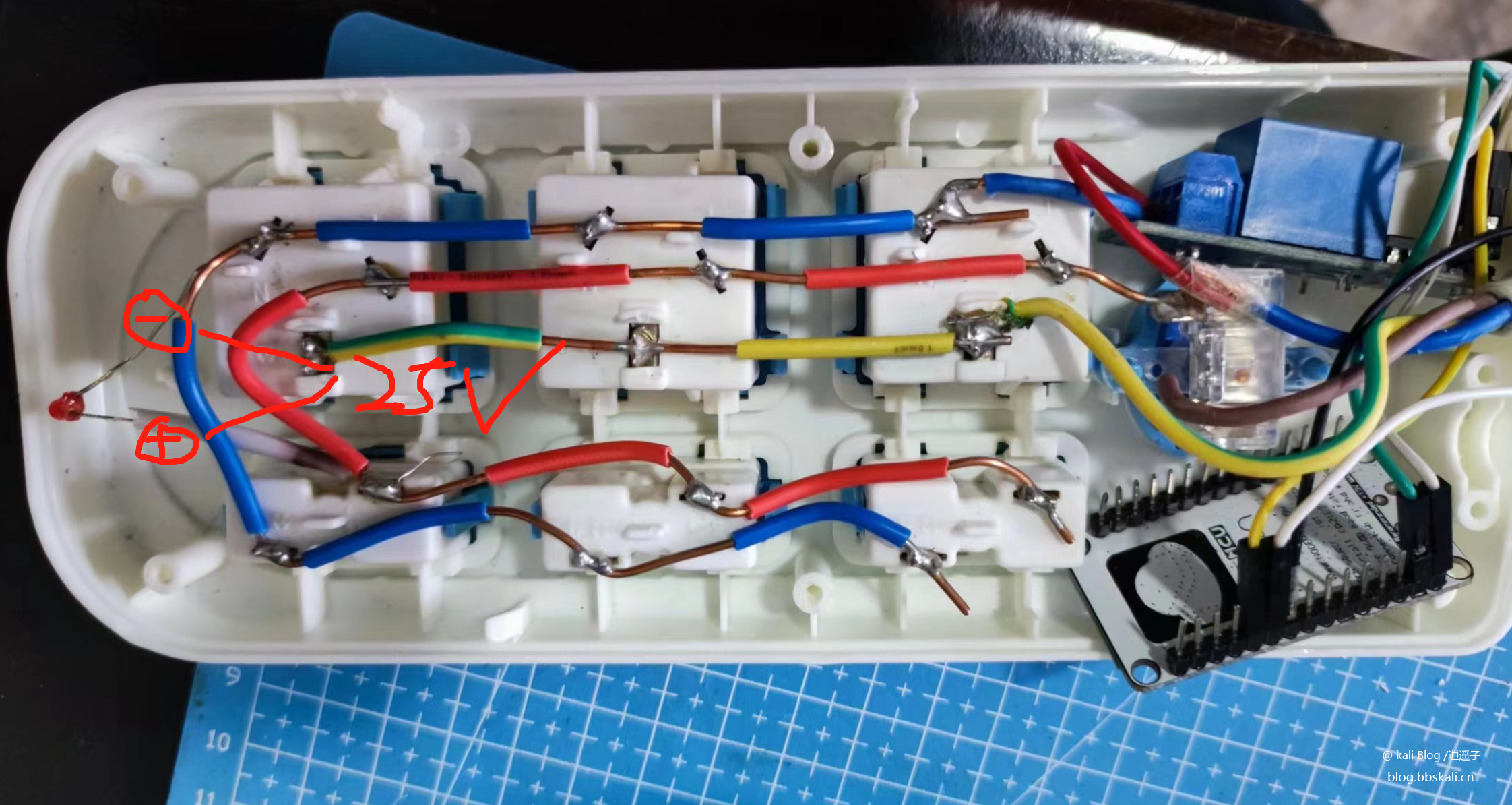
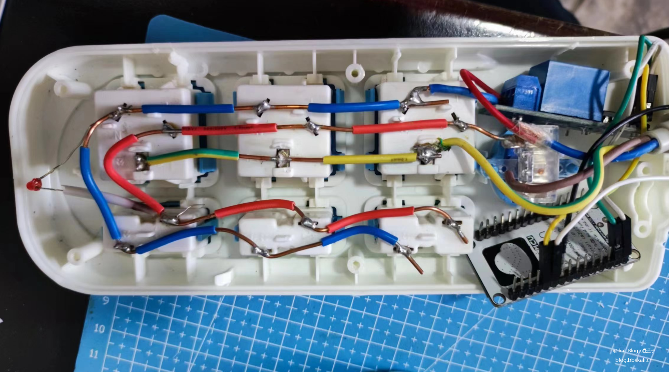
Practical objects
Code
#define BLINKER_PRINT Serial
#define BLINKER_WIFI
#define BLINKER_MIOT_LIGHT
#include Blinker.h
char auth[]='3aa44d779593';
char ssid[]='PDCN';
char pswd[]='1234567890';
//Create a new component object
BlinkerButton Button1('btn-abc');
BlinkerNumber Number1('num-abc');
int counter=0;
//Press the key and execute the function
void button1_callback(const String state) {
BLINKER_LOG('get button state: ', state);
digitalWrite(LED_BUILTIN,digitalRead(LED_BUILTIN));
}
//If an unbound component is triggered, the contents of it will be executed
void dataRead(const String data)
{
BLINKER_LOG('Blinker readString: ', data);
counter++;
Number1.print(counter);
}
void miotPowerState2(const String state)
{
BLINKER_LOG('need set power state: ', state);
if (state==BLINKER_CMD_ON) {
digitalWrite(LED_BUILTIN, LOW);
BlinkerMIOT.powerState('off');
BlinkerMIOT.print();
}
else if (state==BLINKER_CMD_OFF) {
digitalWrite(LED_BUILTIN, HIGH);
BlinkerMIOT.powerState('on');
BlinkerMIOT.print();
}
}
void setup() {
//Initialize the serial port
Serial.begin(115200);
#if defined(BLINKER_PRINT)
BLINKER_DEBUG.stream(BLINKER_PRINT);
#endif
//Initialize the IO with LED
pinMode(LED_BUILTIN, OUTPUT);
digitalWrite(LED_BUILTIN, HIGH);
//Initialize blinker
Blinker.begin(auth, ssid, pswd);
Blinker.attachData(dataRead);
Button1.attach(button1_callback);
BlinkerMIOT.attachPowerState(miotPowerState2);
}
void loop() {
Blinker.run();
}
Video Demo
Problem to be solved
At present, the problem is how to power esp8266. Thinking of directly using the voltage of the indicator light to power the ESP. However, the voltage was measured with a voltmeter and found to be 25v. The voltage is too high. A resistor is required in series. But there is no suitable resistor available on hand. So let it go first!