


By HireHackking in HACKER
· 1 view
esp8266 is mainly used for IoT development and can be used with a variety of sensors to achieve our needs. In this article, let’s enter the world of esp8266 together!
esp8266 development line
Line 1: To lose your hairstyle, you need to write the code of the relevant sensors yourself to solve various dependency libraries. You need to purchase a public network server to solve problems such as intranet penetration. Time-consuming and labor-intensive, poor work efficiency. Line 2: If you have a hand shape, you can just use blinker and other platforms to connect our equipment. The official code base is rich and there are many developers. There is no need to purchase a public network server, and it is more convenient to connect with voice assistants from various domestic mobile phone platforms. Such as Xiao Ai’s classmate, Tmall Elf, etc.
Preparation
Hardware preparation
esp8266 (a few dollars per, free shipping, must) DuPont cable (must) sensor motor servo, etc. (purchase according to your actual situation)
Software Preparation
Arduino IDEblinker APP (used to operate IoT devices)
Environment Configuration
Run the development tool Arduino IDE Click the file - Preferences - Development Board management address to fill in the following domain name: https://arduino.me/packages/esp8266.json (You can increase or decrease it yourself according to your actual situation in the later stage.) 
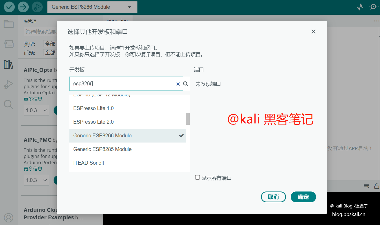
Then click Tools - Select other development boards to search according to your board situation like mine is 8266.
After selecting the corresponding board, automatically download or manually download the corresponding library (recommended to download manually, if the network does not work, hang up the agent) 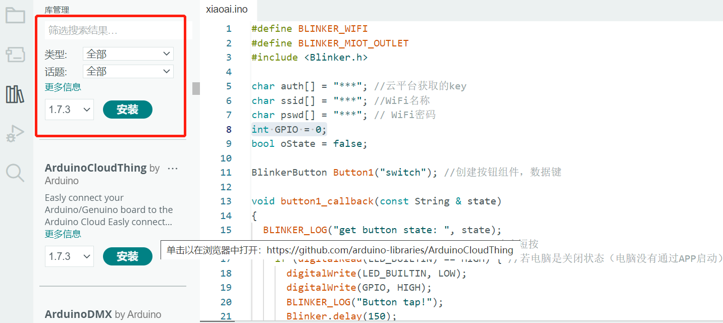 Load the Blinker library because we want to develop based on Blinker, so we need to download its library. After the download address (https://dianandeng.tech/dev) is completed, add the .ZIP library through the Arduino IDE menu project loading library to the library, as shown in the figure
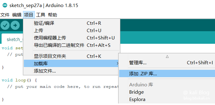
At this point, the development environment configuration is completed.
Hello Word
01 Add device in the app and get Secret Key
Enter the App, click the "+" sign in the upper right corner, and then select Add device Click to select Arduino WiFi access copy the Secret Key you applied for
02 Compile and upload the sample program
Open the Arduino IDE and open the example via file example BlinkerBlinker_Hello/Hello_WiFi.
Find the following variables in the program, fill in the Secret Key (auth) you applied for, the WiFi hotspot name (ssid), and the password (pswd) you want to connect to.
char auth[]='abcdefghijkl'; //The Secret Key obtained in the app in the previous step
char ssid[]='Xiaoyaozi'; //Your WiFi hotspot name
char pswd[]='123456789'; //After your WiFi password is configured, compile first and then upload.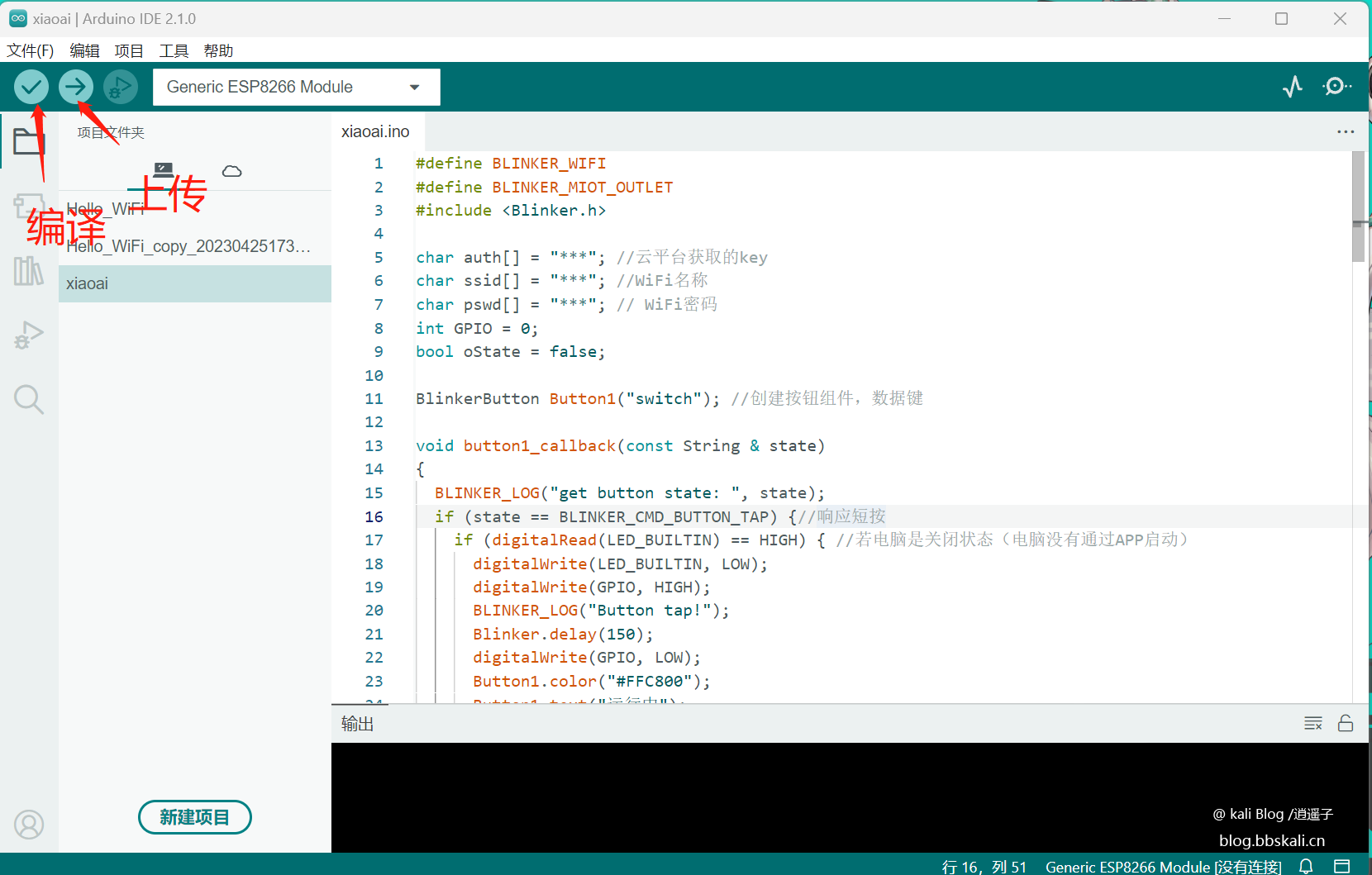
Then you can see in the mobile app that the device has been launched.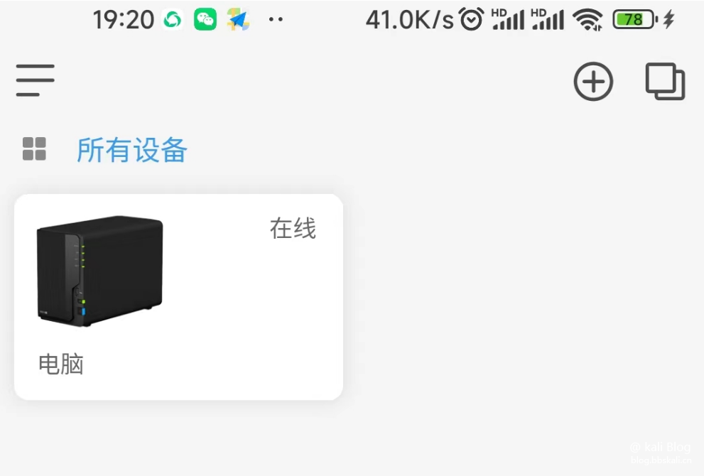
Of course, the name and icon can be changed.
03 DIY interface
On the device list page, click the device icon to enter the device control panel. When you enter the device control panel for the first time, the guide page will pop up. Click Load example on the wizard page to load the sample components.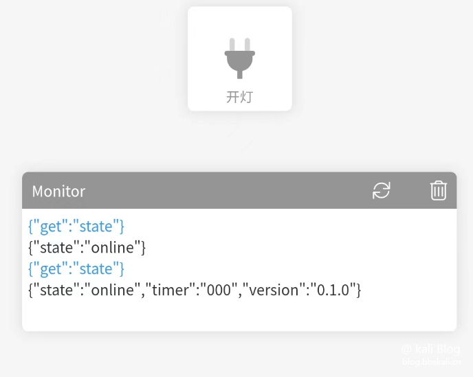
Remote switch based on ESP8266
Let’s take a look at the final effect first.
[dplayer url='https://blog.bbskali.cn/you/m3u8/xiaoai.m3u8' pic='https://blog.bbskali.cn/usr/uploads/2023/03/260347764.png' danmu='false'/]
Preparation
esp8266 development board DuPont line voltage meter (optional) power bank (optional)
How to eat
Compile the following code to the firmware. Two wires connect the GND (negative electrode) of the development board at one end and the GPIO0 end to the power socket of the motherboard.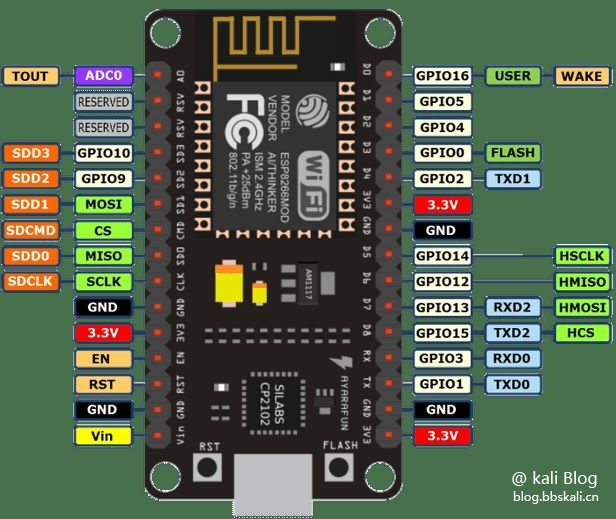
#define BLINKER_WIFI
#define BLINKER_MIOT_OUTLET
#include Blinker.h
char auth[]='5fdb51bc1d31';
char ssid[]='PDCN';
char pswd[]='1234567890';
int GPIO=0; #Define pin to gpio0
//Create a new button object The same name as the button in your DIY page is kali
BlinkerButton Button1('kali');
int counter=0;
//Diy button code, if you just want to use Xiaoai, you can delete it directly here.
void button1_callback(const String state)
{
//Start event
BLINKER_LOG('get button state: ', state);
if (state==BLINKER_CMD_BUTTON_TAP) {//Response short press
if (digitalRead(LED_BUILTIN)==HIGH) { //IF High status
digitalWrite(LED_BUILTIN, LOW); //The light is off
digitalWrite(GPIO, HIGH); //Turn off high
BLINKER_LOG('Button tap!');
delay(300); //Define 3s
digitalWrite(LED_BUILTIN, HIGH); //Restart high level
digitalWrite(GPIO, LOW); //High level input light is on
Button1.color('#FFC800');
Button1.text('Running');
Button1.print();
}
}
//Shutdown event
else if (state==BLINKER_CMD_BUTTON_PRESSUP) {//Response long press and initialize the state to shut down
if (digitalRead(LED_BUILTIN)==LOW) { //If the computer is on (the computer starts through the APP)
digitalWrite(LED_BUILTIN, LOW);//Relay is connected
BLINKER_LOG('Button pressed!');
Blinker.delay(5000);
digitalWrite(LED_BUILTIN, HIGH);//eps-01s light off
digitalWrite(GPIO, LOW);//The relay is disconnected after 5 seconds, which is equivalent to long pressing the computer boot button for 5 seconds
Button1.color('#CCCCCC');
Button1.text('Initialization');
Button1.print();
}
}
}
//The button event ends
//If an unbound component is triggered, the contents of it will be executed
void dataRead(const String data)
{
BLINKER_LOG('Blinker readString: ', data);
counter++;
Number1.print(counter);
}
//Introduce small love
void miotPowerState(const String state)
{
BLINKER_LOG('need set power state: ', state);
if (state==BLINKER_CMD_ON) {
digitalWrite(LED_BUILTIN, LOW);
BlinkerMIOT.powerState('off');
delay(500);
digitalWrite(LED_BUILTIN, HIGH);
BlinkerMIOT.powerState('on');
BlinkerMIOT.print();
}
else if (state==BLINKER_CMD_OFF) {
digitalWrite(LED_BUILTIN, LOW);
BlinkerMIOT.powerState('off');
BlinkerMIOT.print();
}
}
void setup()
{
//Initialize the serial port
Serial.begin(115200);
BLINKER_DEBUG.stream(Serial);
BLINKER_DEBUG.debugAll();
//Initialize the IO with LED
pinMode(LED_BUILTIN, OUTPUT);
digitalWrite(LED_BUILTIN, HIGH);
//Initialize blinker
Blinker.begin(auth, ssid, pswd);
Blinker.attachData(dataRead);
Button1.attach(button1_callback); //Initialize button parameters
BlinkerMIOT.attachPowerState(miotPowerState);//Initialize the parameters of Xiaoai
}
void loop() {
Blinker.run();
}
Core Code Interpretation
digitalWrite(LED_BUILTIN, LOW);
BlinkerMIOT.powerState('off');
delay(500);
digitalWrite(LED_BUILTIN, HIGH);
BlinkerMIOT.powerState('on'); When the computer is turned on, the two-wire connection heads need to be disconnected. Therefore, I added the time parameter delay(500); first power on the device, then after 500ms, it is enough to turn off the power.
Problems facing
Because after the computer is turned off, there will be no clicks on the motherboard, powering esp8266 is a big problem. Therefore, you need to use the voltmeter to measure that pin has a voltage of more than 3v when the computer is turned off. Then use the motherboard to power esp8266. But my motherboard is the motherboard from 20 years ago. I was as fierce as a tiger when I was running, but I found that there was only one pin voltage of 0.8v. In the absence of any help, I used the USB port of Guangmao to directly power esp8266. It's been solved!
Door to Xiaoai
1Open Mijia App. Through my other platform devices, click Add Lighting Technology to bind the account, and bind the blinker account 2. After the binding is successful, the blinker device that supports Xiaoai’s control will appear in the Lighting Technology Device List of My Other Platform Devices 3. You can now use Xiaoai to control the device
Recommended Comments